Arts + Entertainment
Live Performances
Museums + Art Displays
Pop-Ups
Signage
Studios + Sound Stages
TV + Film Production
Theaters
Theme Parks + Playplaces
discover
Education
Colleges + Universities
Private + Specialty Schools
Public K-12
discover
Energy
Solar Energy
Transmission Infrastructure
Wind Energy
Oil + Gas
discover
Government
Municipal
State
Federal
discover
Healthcare
Senior Care
Hospitals
Outpatient Facilities
discover
Industrial
Heavy Industrial
Warehouse + Distribution Centers
Industrial Ports + Terminals
discover
Ports + Coastal
Berths, Piers + Wharves
Bulkheads
Esplanades
Ferry Landings, Ship Terminals
Floating Structures
Ports + Terminals
Marinas + Breakwaters
Transfer Stations
discover
Public Infrastructure
Bikeways + Trails
Garage + Parking Facilities
Park + Recreational Spaces
Streetscapes
Utility Infrastructure
Water + Wastewater
discover
Real Estate Development
Commercial
Community Facilities
Mixed-Use
Multifamily Residential
discover
Transportation
Airports
Bridges
Ports + Terminals
Rail Transportation
Roads + Highways
Ropeway + Linear Infrastructure
discover
Floating Harbor Wetland
Multimodal Processing Plant
416 + 420 Kent Dynamic Highrise
Wittpenn Bridge
Tiffany Crane
LaGuardia Airport Terminal B
NYC Ferry
Orlando Airport LED Displays
A leading full-service engineering firm renowned for our trusted, high quality, and innovative approach to solving complex challenges.

Expert Insight

Wittpenn Bridge Steel Precision

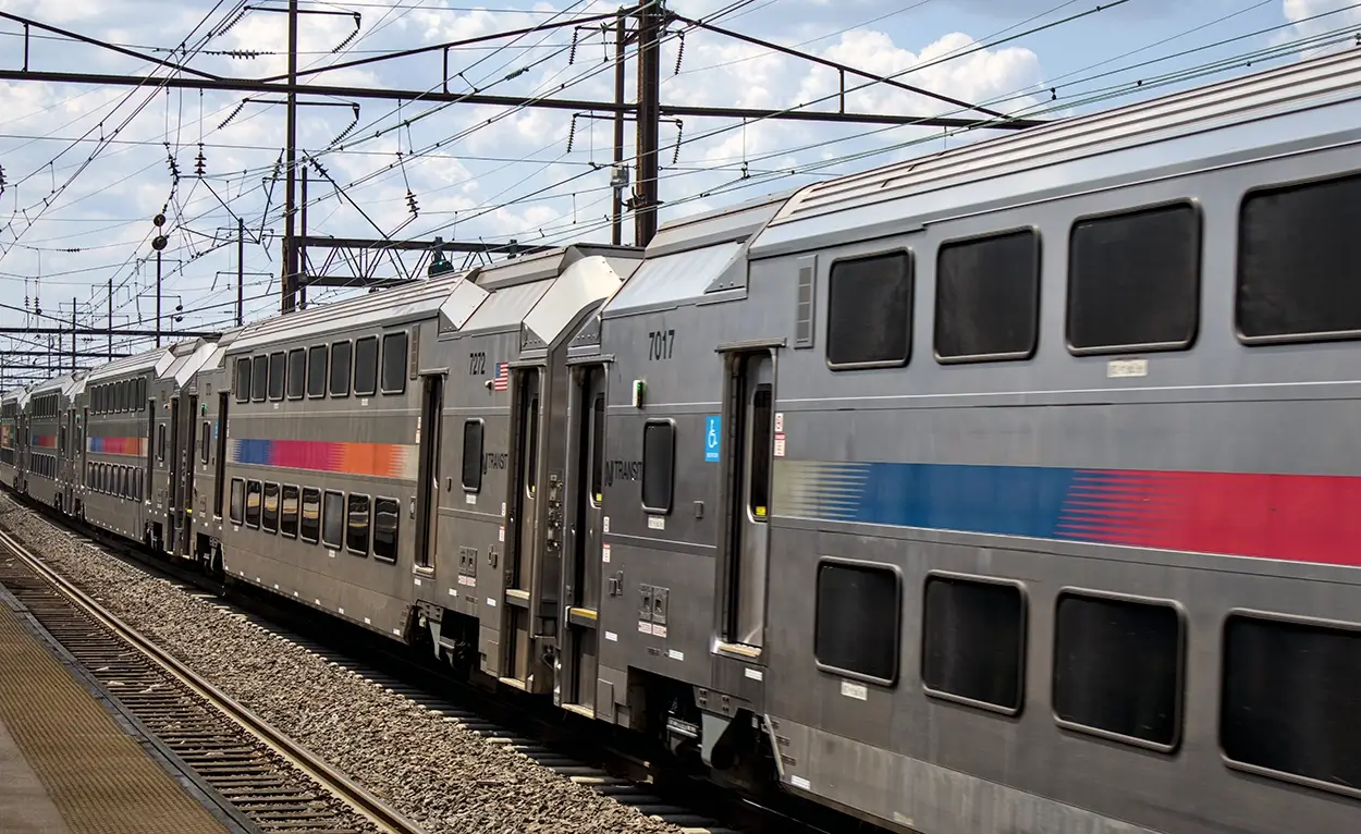
The new 3,277 ft. long Route 7 Wittpenn Bridge, New Jersey’s first orthotropic bridge, is an integral component of the State’s Portway Corridor project and a symbol of its renewed emphasis on infrastructure redevelopment.

Replacing a deteriorating vertical lift truss bridge built in 1930, whose four 10-foot travel lanes did not include any shoulders nor had any physical separation between opposing traffic, the new vertical lift structure, designed by Jacobs, is wider and safer than its original. In addition to shoulder and median placement, the vertical clearance was doubled from 35 to 70-feet in the closed position, reducing the frequency of bridge openings that affect marine and vehicle traffic.

Wittpenn Bridge Steel Precision
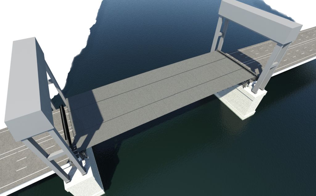
Rendering

New Jersey Department of Transportation (NJDOT) divided the project into five separate contracts, allowing work on different portions to take place simultaneously. The third contract, awarded to CCA Civil, included the erection main span vertical lift towers and the main lift span comprised of three steel box girders and steel orthotropic deck system.

Nearly impossible to achieve without the strength of steel, the new Wittpenn Bridge’s main lift span measures 324 feet long and 110 feet wide and weighs in at nearly 2500 Tons. Fabricated by Vigor, the bridge design features a unique orthotropic deck system, with integrated floor beams and box girders, where the ¾” thick deck serves as the top flange to the U-ribs, transverse floor beams and primary box girders. This integrated system not only makes the bridge more efficient for such a long span but also allows the deck to directly bear vehicular traffic loads, with only a thin wearing surface for texture. This system reduces the overall weight, improves construction schedule and minimizes long-term maintenance. McLaren Engineering Group’s construction team was contracted by CCA Civil to serve as the project’s erection engineers and tasked with helping meet the strict contract tolerances, of which included erecting the bridge within a 16th of an inch over 324 feet in the longitudinal deck joints. The challenge required innovative engineering solutions in the development of erection sequences and means and methods, temporary works, crane plans and custom rigging solutions. All of this was closely coordinated with Vigor who used state-of-the-art fabrication technology/equipment, like 3D scanners, CNC plasma cutters and Robotic welders, to ensure the highest level of accuracy in fabrication. Vigor also mimicked the proposed erection sequence in their yard, not only to ensure contract tolerances were met, but also to vet the proposed sequence/procedures, work out any kinks, and ensure seamless erection in the field.

Crane
Engineering

Wittpenn Bridge - Rigging and Heavy Lifts
Wittpenn Bridge Crane Construction
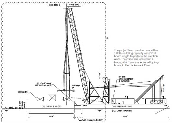
Given the massive weight and scale of the box girders with integrated orthotropic steel deck, the project team utilized a Donjon Chesapeake 1000 crane, one of the largest heavy lift cranes on the east coast, with 1,000 tons in lifting capacity and 231 feet in boom length, to perform the erection work. Tugboats moved the crane barge into place. Three, longitudinally split, nearly 700-ton deck spans were lifted into place, one-a-day, and the ¾” thick deck was field welded together with a full-penetration weld (that is 644ft of total weld length). Given the overall span geometry, the main span (box girders and end floor beams) would only fit between the approach spans and lift towers once it was fully assembled. With that, McLaren designed temporary shoring towers to raise the bridge elevation approximately 18ft during erection and slide rail systems to support the erection procedures. The bridge was erected on temporary shoring towers, which allowed the end floor beams to be slid back onto the approach span while erecting the three box girder sections. Following the erection of the box girders, the end floor beams were then slid into position, tight to the ends of the box girders where the bolting process to connect the boxes to the end floor beam would begin.
Wittpenn Crane Drawing

Because the bridge was being erected 18 feet above its final location, the counterweight had to be erected 18 feet below its final contract elevation to maintain contract geometry. McLaren designed temporary link bar extensions to suspend the counterweight so that the relative distance from the bridge up around the sheaves on the top of the lift towers and down to the counterweight, was the same.

Positioning where the pick points were was critical to the stability of the bridge. During the pick, stresses in the box girders were reversed, putting portions of the bottom flange and web into compression, yet the bridge was not designed for this condition. As such, the bridge did not have longitudinal web stiffeners at the bottom of the box girder. McLaren coordinated with Donjon Marine and developed crane pick plans for the Chesapeake 1000 which maximized the reach capacity of the crane and ultimately maximized the spread of the pick points on the box girders. This enabled the reduction of negative flexure in the bridge sections during their pick. A Finite Element Analysis of the bridge was developed to check the global stability of the box elements for this temporary condition and to perform a local buckling analysis of the box girder webs, specifically near the pick points. Lifting lugs were designed and integrated into the web of the box girder by upsizing the thickness of the web steel plates in this portion of the box, welding it to the adjacent web plates, and allowing it to protrude through the top of the deck to create a continuous portion of the web plate up through the bridge deck. Stiffeners and cheek plates were added to the web extension on the topside of the bridge deck to complete the make-up of each lifting lug. This lug design eliminated the risk of lamellar tearing in the deck plate, which could be a failure mode if the lug was just welded directly to the deck plate.

Steel Precision
Connection Design

The individual deck span sections were connected to two end floor beams – each in the neighborhood of 200 kips. However, due to the self-weight of the bridge and camber in those floor beams, the bolt patterns to connect the box girders wouldn’t line up in a zero-load condition. To solve for this, McLaren worked with Vigor to initiate incremental connection and load transfer procedures. First the middle box girder was connected with only 50% of the bolts and then unloaded slightly to release some of the camber in the end floor beams. This allowed more bolt holes to line up and be connected. After erection of the middle box girder, about 80% of the camber was out of the end floor beam, allowing the team to move on to connecting the two exterior box girder sections in similar fashion. In final condition, the box girders are supported at the ends as a simple span bridge.

Vertical Lift
Towers

Wittpenn Bridge Vertical Tower Crane Lift
Vertical Tower Crane Lift

Each of the moment frame permanent vertical lift towers were comprised of four tower legs, two transverse cross beams and two top sheaves, a total of 16 major picks upwards of 200k. All of these major tower components were erected using Weeks Marine 533 Barge Crane with 360-degree rotation. Due to the eccentricities, the tower sections required custom rigging and pick plans in order to ensure a level lift that dropped smoothly into place. Additionally, a staged analysis of the towers was performed during erection to ensure stability during temporary conditions. It also helped guarantee that interim deflections encountered during erection would not impact the overall shape of the final erected tower and that there wouldn’t be any issues with steel fit-up during erection.

Wittpenn Bridge
Sucess

Wittpenn Bridge Steel Precision
Wittpenn Bridge Open, courtesy of CCA Civil

The Wittpenn Bridge replacement project required intensive pre-planning and coordination with the New Jersey Department of Transportation, subcontractors, vendors, and work crews to ensure a safe and coordinated operation. In the end, the team delivered a successful project and completed the erection of the main span.

Opened on October 1st, 2021, just 200 ft. north of the original structure, the new Wittpenn Bridge is delivering a safer and less congested crossing of the Hackensack River between Jersey City and Kearny. Some of the next phases, like connection of exits, demolition of the old bridge, and its approach roads, is already underway.

Questions about Wittpenn Bridge Steel Precision?